Ethernet
Most of us use Ethernet in some way or another. Ethernet describes a family of wired computer networking technologies. While most of us opt for Wi-Fi due to convenience reasons, Ethernet powers the servers and data centers which deliver the services we enjoy.
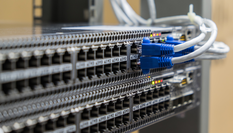
I’ve always wondered what goes on after I plug in a CAT 5E cable into my switch. Previously, it would be a simple matter of plug-and-play (or plug and PuTTY in). Having recently learnt about Operating Systems, Digital Signal Processing, Communication Systems and Computer Architecture through courses at Imperial, combined with hands-on experience with Software Defined Networking and some exposure to 5G core through my work at AWS, I thought it would be time to re-examine this phenomenon. I also recently chanced upon Container Network Operating Systems and the SONiC ecosystem, which made me rediscover my interest in networking.
Do note that this post can get quite lengthy. I recommend you use the table of contents and jump to the respective OSI layer that you are interested in.
Network Interface Card
The critical bit that I did not know about before college was the role of the Network Interface Card (NIC). NICs are hardware components that connect a computer or device to a network. It provides an interface between the device and network medium, enabling data to be transmitted and received. While NICs operate on Layer 2 of the OSI Model, they interrupt the CPU and interact with drivers, which interface with the operating system - so they actually have impact across different OSI layers.
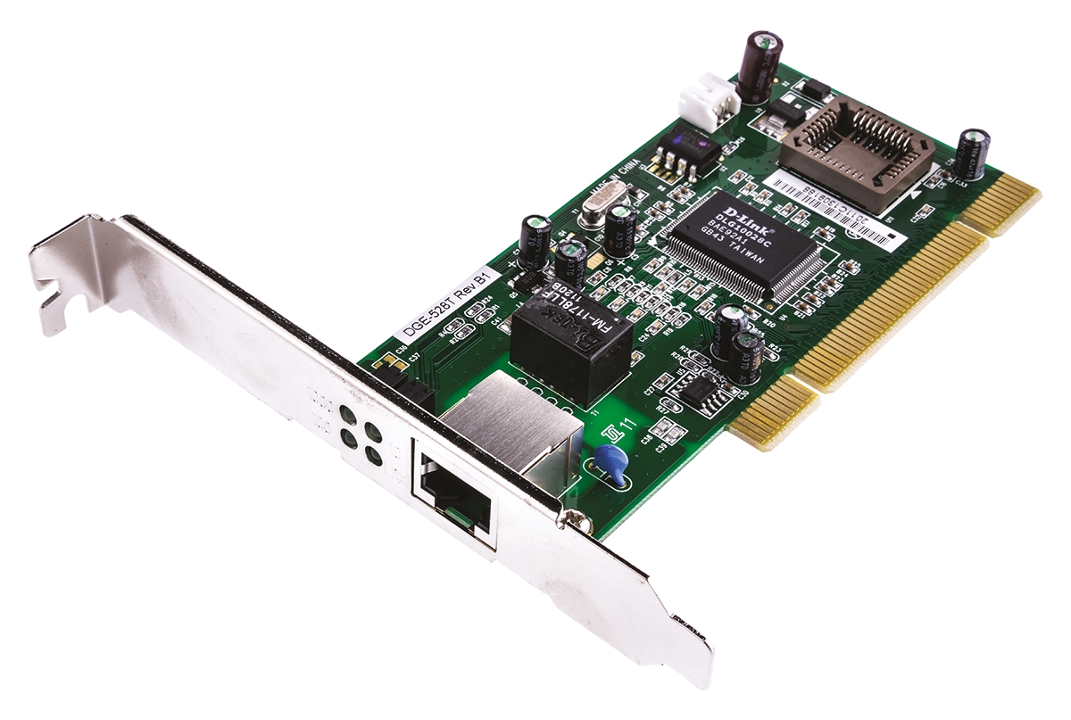
Interestingly, Virtual Machines (VMs) also have NICs - virtual ones (vNIC). Virtualisation emulates hardware components, including network adapters. Hypervisors create a virtual switch that handles communication between VMs and the physical network, with each vNIC connected to the virtual switch. Containers too have virtual network interfaces, which I previously worked with when I set up a docker network for my Year 2 Project. When a Docker container is created and a network is specified (think Docker Compose), Docker sets up a pair of virtual Ethernet interfaces, with one end attached to the Docker host network namespace, and the other inside the container network namespace.
Layer 1 - Physical
Back to the journey of a frame. We will explain this using the OSI layers as a framework - the benefit is that we can separate each layer and each layer doesn’t depend on other layers. Think of a CAT 5e cable plugged into a switch. Now, raw electrical signals representing the Ethernet frame are received by the NIC in the switch (a frame is, like most data, fundamentally 0s and 1s). These signals are transmitted over physical medium - copper wires in this case. This section explains how the NIC hardware processes signals to extract bits that contain the Ethernet frame.
Twisted Pair - Electrical Signals
Ethernet is powered by twisted pair technologies. What this means is that in each cable, we have eight wires - this is to increase bandwidth and to support various networking standard. Twisted pair - as the name implies - means that each wire is actually a twisted pair of copper wires.
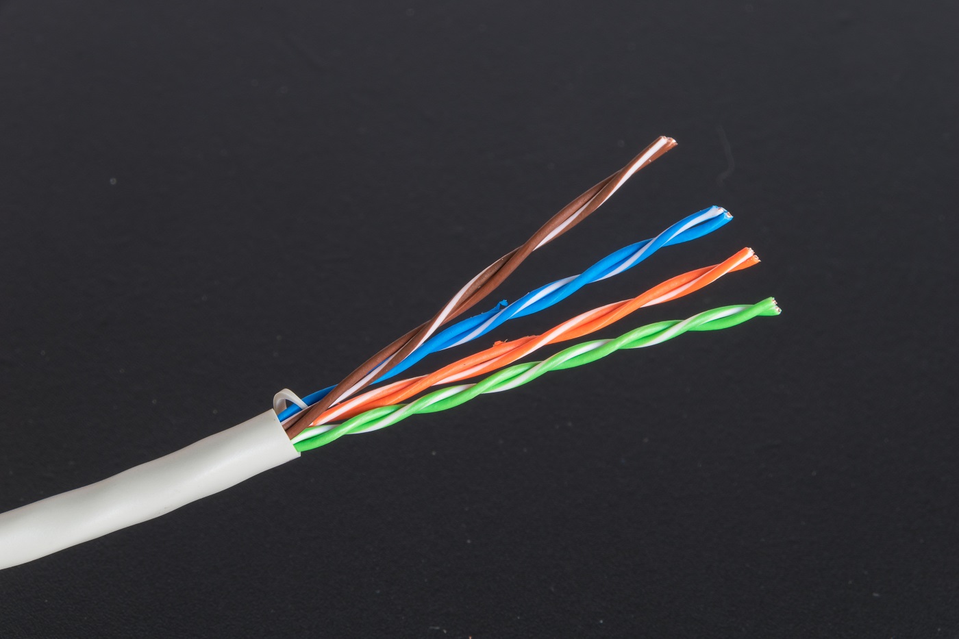
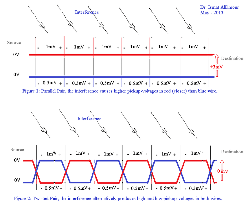
This enables differential signalling, where one wire carries a higher voltage (a 1 bit) and the other, a lower voltage (a 0 bit). This reduces electromagnetic interference and improves cable noise immunity.
We have four pairs of wires to give us higher bandwidth and data rates - critical for Gigabit Ethernet. One area of confusion I had was - when I crimped 5e cables, I crimped them in ‘straight-through’ configuration - where is the twisted pair? I later realised that twisted pair means that the cables are twisted within the cable, but we align them in order when crimping.
Encoding and Line Codes
Now, we will explain more about encoding and line codes, why it matters and how it works - specific to wired Ethernet. We seldom send raw data over serial connections - for example, if you received a stream of zeroes - how do you know whether that’s raw data or no signal? This mandates the requirement for an encoding scheme. I will be explaining 8b/10b encoding, which is a line code that maps 8-bit words to 10-bit words. This is used in Gigabit Ethernet.
Suppose that we want to encode an 8-bit stream - 10111001.
We use a lookup table to map the 8-bit binary data to a 10-bit symbol - from 10111001 to 0100100111.
This creates a neutral running disparity (the difference between 0s and 1s) of 0.
We maintain running disparity within acceptible limits. So 0100100111 does not have more than five consecutive 0 bits or 1 bits.
We transmit 0100100111 over the communication medium, retaining DC balance and running disparity properties, ensuring signal integrity. This also makes it easier to distinguish between data and no-transmission situations.
8b/10b encoding also lets us demarcate the end of a frame by identifying unused symbols which specifically never appear within actual data inside the frame. For example, we can designate the 10b symbol 1100001100 as the end-of-frame marker.
Frame Preamble and Start Frame Delimiter
Now we understand how bits are encoded and decoded by the NIC. We can therefore dive into the structure of the Ethernet frame. The frame has a preamble, which performs clock synchronisation between the receiving device and the incoming signal. How does this work?
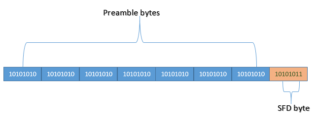
Ethernet does not have a shared bit-clock (since none of the pins / conductors carries a clock signal). Hence, the receiver must synchronise the bit clock to the sender’s block with every packet. The preamble allows the receiver’s Phase Locked Loops (special circuits to synchronise bit clocks) to have enough time to lock into synchronisation with the sender before data bits are transmitted. Interestingly, we can think about why are 7 bytes needed for this - since the release of the 802.3 standard, have PLLs improved to the point where less than 7 bytes are needed? But changing things would be too much of a hassle.
The preamble is then followed by the Start Frame Delimiter (SFD), which is immediately followed by the destination MAC address. The SFD is distinguished from the Preamble because it consists of one byte that ends with 1 instead of 0.
Layer 2 - Data Link

Great! Now we can move on to MAC addresses. MAC stands for Media Access Control - a unique identifier assigned to the NIC.
Let us start by defining the main ‘features’ of a NIC:
- It has a MAC Address that can be used to filter incoming packets
- It has a ring buffer to store packets received
- It has a ring buffer to store packets to be sent
- It can generate interrupts to the CPU
- We can program all of the above
Physical Addressing
The MAC Address is first checked to see if the NIC’s MAC Address matches the destination MAC Address inside the frame. If this is a match, the frame is further processed; else if it is also not a multicast or broadcast packet, it is discarded.
NICs can be put into promiscuous mode to place every frame received into the ring buffer regardless of destination MAC address.
Error Correction - Frame Check Sequence (FCS)
The frame contains a four-octet cyclic redundancy check (CRC) that lets us detect corrupted data within the frame. FCS is a value that is computed as a function of protected MAC frame fields - source and destination address, length/type field, MAC client data and padding.
This computation is often a left shift CRC-32. CRC can be implemented in hardware via a left shifting Linear Feedback Shift Register (interestingly, I implemented this in SystemVerilog for an unrelated class project).
Frame Filtering
We can also implement filters at the MAC address level - with whitelists and blacklists for source MAC addresses. However this can be circumvented using packet analysis to find valid MAC addresses, and then performing MAC spoofing.
Buffering
If all checks pass, the frame is stored temporarily in memory as a ring buffer. This buffer allows for efficient handling of incoming frames, especially when the NIC operates at higher speeds than the rest of the system.
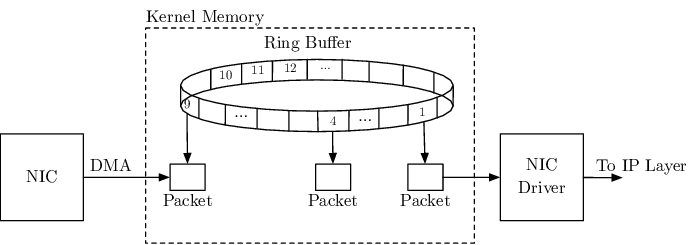
A ring buffer is used as the data structure for storing frame data because (1) they consume a fixed amount of memory and (2) handle the model of single producer single consumer well. In a ring buffer, the producer places data in the buffer and moves a head pointer, while the consumer removes data from the buffer, moving the tail pointer.
The ring consists of multiple entries, with each entry called a descriptor. A descriptor is made up of three parts: (1) a buffer address, (2) a buffer length, and (3) packet metadata.
Interrupt Generation
When a packet arrives, the network card will generate an interrupt, letting the OS know that it should check the ring.
Layer 4 - Transport
How does the CPU handle incoming data? What are the mechanisms to process the incoming Ethernet frame?
Receive Side Scaling
A naive implementation of this process will inevitably cause performance issues. Hence, there is a need to optimise. Assume that we have an interrupt that fires whenever packets are successfully received or transmitted. If there was only a single interrupt used and that vector maps to a single CPU, that one CPU would process the entire stream of packets. In many systems - the CPU would process that packet all the way thorugh the TCP/IP stack until it reaches a socket buffer for an application to read.
This creates problems - (1) that CPU is spending all its time handling interrupts, and is unable to do user work; (2) this might cause increased latency for incoming packets due to processing time.
This problem was especially prevalent on early single CPU systems. Many systems only had a single socket with a single CPU, with no hardware threads and cores. So as new platforms began to enable multi-processing, there needed to be a way for NICs to take advantage of horizontal scalability.
While we could use multiple threads for the same ring, this causes problems as well - instead of a single CPU being 100% busy, we will end up with several CPUs busy and spending a lot of time blocked on locks. The problem is that shared state still exists in the form of the ring itself.
Furthermore, TCP also implements logic to deal with out of order packets - in many TCP stacks, when a packet is out of order, network throttling or retransmission will occur, injecting notable latency and performance impacts (read my Software Systems study notes for more information here).
With lock ordering and the scheduler, packets can easily arrive out of order. So we need to make sure that we don’t allow packets to be delivered out of order, and we also want to avoid sharing data structures protected by the same lock.
The first solution is to add a bunch more rings to the NIC - so no resources are shared at all.
The second is to deal with out of order packets. One observation is that TCP / UDP connections always go to the same place. What we can do is assign a given connection to a ring. For a given TCP connection, the source and destination IP address and source and destination ports are the same throughout the lifetime of the connection. Thus, we can assign by hashing. NICs have a hash function that takes into account various fields in the header that are constant to produce a hash value.
This ensures that traffic won’t end up out of order. But it won’t be spread evenly amongst the rings.
This technology is called Receive Side Scaling, and it distributes receive processing from a NIC across multiple CPUs.
TCP/IP Protocol Layering and Sockets
While L4 deals mainly with interrupt handling, the TCP/IP protocol stack is maanged by higher layers. The OS networking stack will take into account the protocol of the incoming packet via its IP header, and then send it up the stack via the appropriate socket. Sockets provide an interface for applications to communicate over the network via system calls.
Layer 5 - Network
NICs require specific drivers to interface with the operating system. These drivers handle various tasks related to NIC operation.
Top Half / Botton Half Processing
To effectively manage the incoming frames, NIC drivers split processing into two parts - the top half, which involves quickly acknowledging the interrupt and moving data from the NIC to the kernel, and the bottom half, which performs more resource-intensive processing.
Protocol Handoff
Depending on the protocl of the incoming data, the driver might hand off the packet to the appropriate protocol handler in the OS networking stack.
Interrupt Coalescing
To reduce the overhead of frequent interrupts, NIC drivers often batch multiple received frames into a single interrupt, reducing CPU usage.
Queues
Queues within the NIC are used to manage incoming frames. If queues fill up due to high incoming traffic, there is a risk of dropped frames or buffer overflow. This leads to performance degredation and dropped connection. Thus, queues must be designed to handle bursts of traffic and maintain consistent performance.
Layer 6 - Presentation
Cache Locality and IRQ Steering
Many modern NICs aim to maintain good cache locality by optimising memory access patterns, reducing cache misses and improve data processing speed. Furthermore, IRQ steering can be used to distribute interrupts across multiple cores, improving parallelism and system performance.
Doesn’t that sound like RSS?
IRQ steering is similar to Receive Side Scaling in that both aim to distribute processing tasks across multiple CPUs to improve performance. However, RSS particularly focuses on optimising network traffic processing, while IRQ Steering is more broad and deals with distribuing interrupts from multiple hardware devices.